What you get
A complete analysis of the shell from the scan, without leaving the browser.
Diameter and radius
Radius, diameter, circumference, area and center of each ring, fitted with thousands of wall points.
Roundness
Radial deviation profile degree by degree, out-of-roundness, RMS and arc coverage.
Verticality
With several rings: tank axis, tilt in degrees and mm/m, lean direction and top lean.
3D inspection view
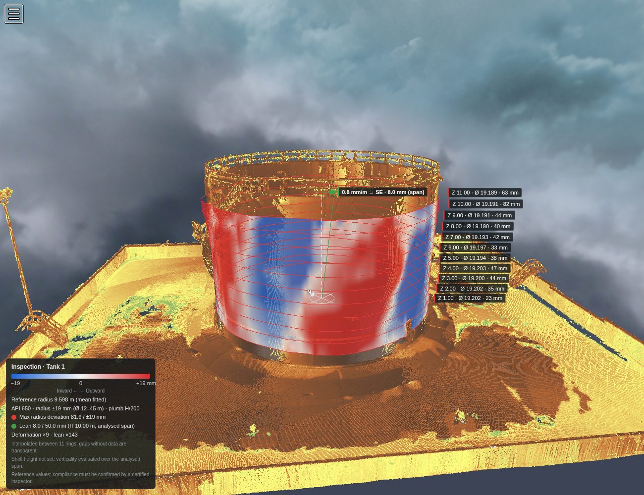
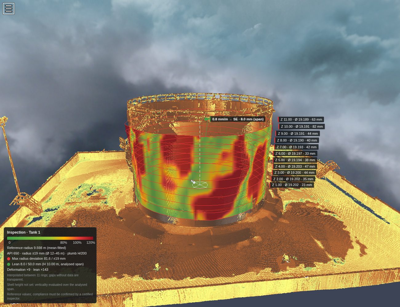
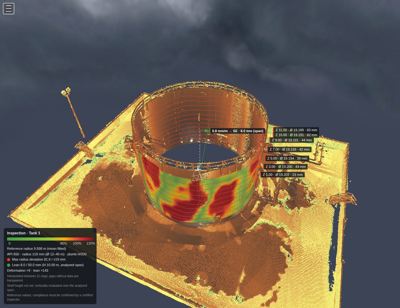
Shell colored by deviation or by tolerance, exaggerated deformation, plumb line and legend.
PDF report
Summary, per-ring tables, radius, deviation and center offset charts.
CAD export
DXF with rings, centers and axis; PNEZD / LandXML points; CSV with one row per ring.
Before you start
| Topic | Details |
|---|---|
| Activation | The section is off by default. The administrator enables it in Project settings → Tanks & Cylinders: Off, Administrators only or Administrators and visitors. |
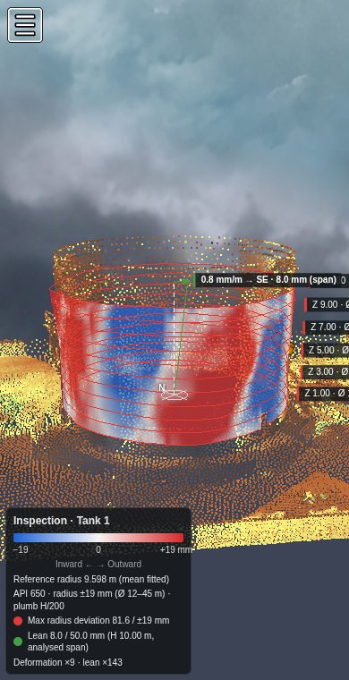
| Device | Analyses run on desktop. Tanks already analysed can be viewed on mobile, including the inspection view. |
| Point cloud | A vertical tank with its wall visible in the scan. The more of the perimeter is covered, the more reliable the result. |
| Where it is saved | Administrators: in the project, on the active layer. Visitors: in their browser if the project allows it; otherwise for the session only. |
Step by step
Open the project in the viewer and expand the Tanks & Cylinders section of the sidebar. The section's ? button brings you to this guide.
1Seed on the wall
Pick wall points: click 3 to 20 points on the tank wall, spread around it. The first point sets the elevation of the ring. The magnifier with snapping helps to place points on the wall.
- Enter or right click: finish.
- Backspace: remove the last point. Esc: cancel.
- Use selected circle: use a circle already drawn in Drawing Layers as the seed.
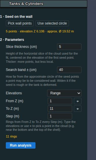
The panel shows the number of points, the elevation and an approximate diameter.
2Parameters and elevations
- Slice thickness (5 cm by default): height of the cloud slice used for each ring. Thicker: more points, less local.
- Search band ± (10 cm by default): maximum distance to the approximate seed circle. Widen it (30–40 cm) if the seed is rough or the tank is deformed.
- Elevations:
- Seed elevation: one ring at the seed elevation.
- Range: from / to / step (min. 0.05 m). The ⌖ button takes the elevation of a point clicked in the cloud.
- List: comma-separated elevations, to skip nozzles, stairs or stiffening rings.
Up to 50 rings per analysis. Several rings give the verticality.
3Run and review
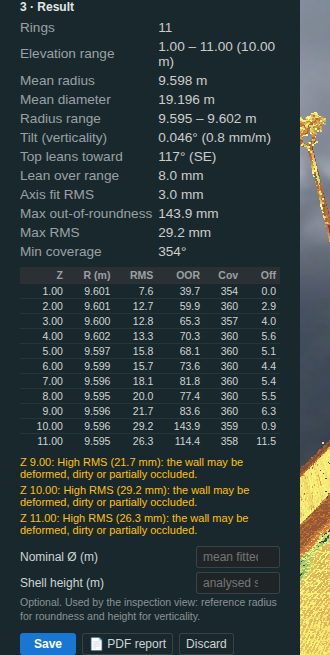
Run analysis reads the cloud ring by ring (it can be cancelled). The first read takes longer because the cloud is downloaded; the next ones are almost instant.
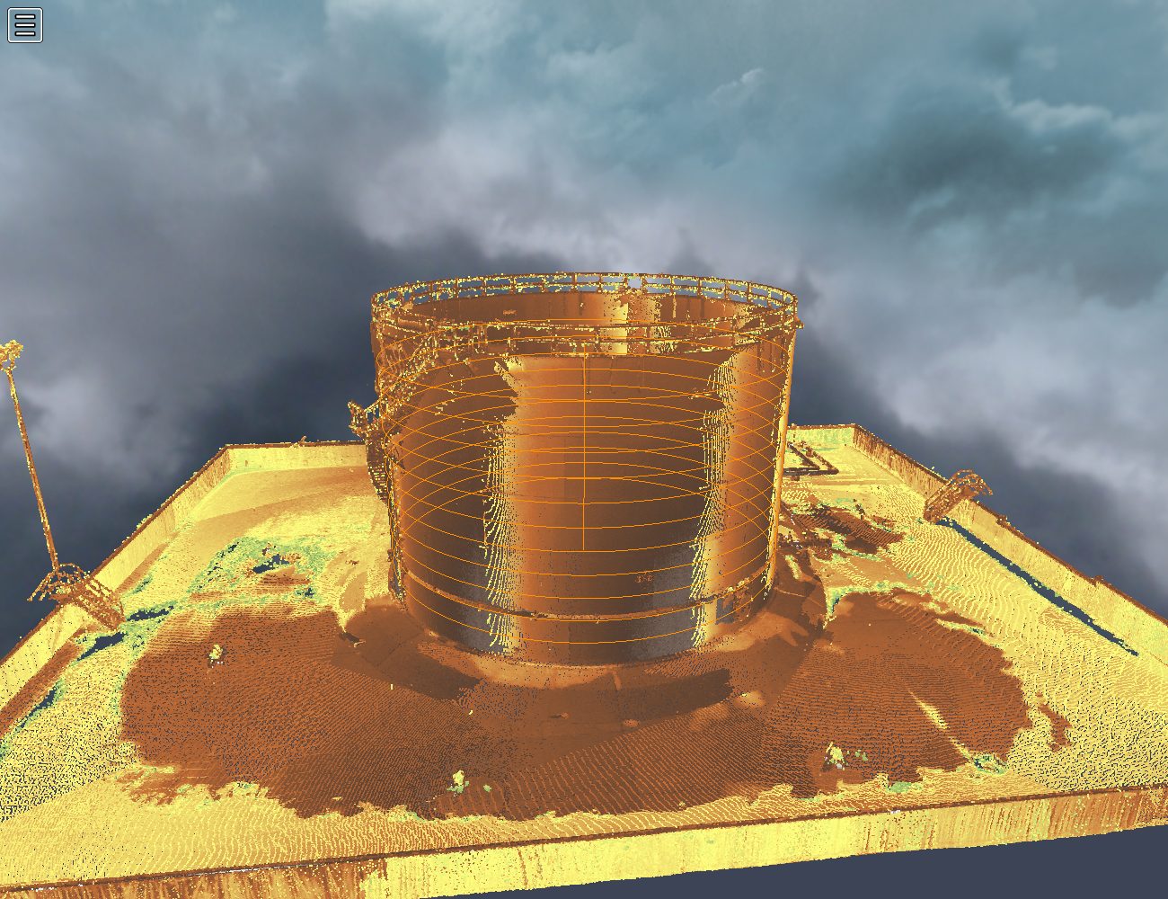
The result appears in the panel (summary, per-ring table and warnings) and in the scene: the rings and the tank axis in orange.
Rings that cannot be fitted (for example above the roof) are skipped with a warning.
4Save
Save adds the tank to Drawing Layers (Tanks group). Administrators store it in the project with the Save button of Drawing Layers, like any drawing.
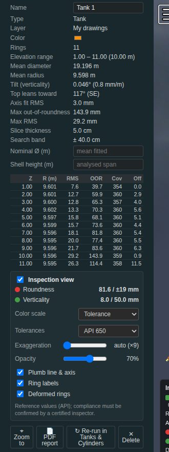
Optional tank data: Nominal Ø (design diameter, the reference for roundness) and Shell height (for verticality). Fill them in before saving or later, in Properties.
↻ Re-run repeats the analysis with the same seed and elevations and replaces the tank when saved.
5Inspection view
After saving, the panel's ◎ Inspection view button opens the tank Properties with the view already on. You can also go to Drawing Layers, select the tank and turn on Inspection view in Properties. The shell is colored over the cloud and the plumb line, axis, deformed rings and legend appear. Details in the next section.
6Report and export
📄 PDF report produces the tank report. The Drawing Layers export includes tanks in DXF, PNEZD, LandXML and a rings CSV.
Inspection view
A representation of the shell built from the ring profiles: it shows instantly, on mobile too, without reading the cloud again.
| Element | What it shows |
|---|---|
| Colored shell | Radial deviation from the reference radius (nominal or mean), interpolated between rings. Areas without data stay transparent. |
| Exaggeration | Automatic or ×1 to ×200: makes millimetre deformations visible on tanks many metres wide. |
| Plumb line and axis | Vertical line from the base (dashed) and the exaggerated real axis, with an arrow toward the lean and a mm/m → direction · lean label. |
| Rings | Real deformed shape of each ring and a Z · Ø · max deviation label in the traffic-light color. |
| Legend | Scale, reference radius, tolerance profile, roundness and verticality checks, exaggerations and notes. |
| Controls | Scale, tolerances (API 650 / API 653), exaggeration, opacity and visible layers, in Properties. |
PDF report
Vector A4 report produced on the server. With several rings it takes two or more pages.
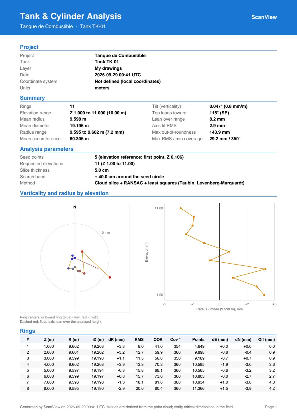

- One ring: results, parameters, plan view with exaggerated deviation and a deviation-by-azimuth chart.
- Several rings: verticality summary, center offsets plan, radius by elevation, per-ring table and overlaid profiles.
- It includes the project coordinate system, Nominal Ø and Shell height when declared, and the quality warnings.
CAD export
| Item | DXF | PNEZD / LandXML |
|---|---|---|
| Ring | CIRCLE at its elevation (3D) or at Z = 0 (2D), layer <LAYER>_TANK_* | — |
| Center | POINT on <LAYER>_TANK_CEN_* | CEN <name> point per ring |
| Seed | POINT on <LAYER>_TANK_PTS_* | — |
| Axis (several rings) | LINE on <LAYER>_TANK_AXIS_* | — |
| Rings table | CSV in the ZIP: elevation, center, radius, diameter, RMS, out-of-roundness, coverage, points, offsets and deviation from the reference radius. | |
How it is computed
- Initial circle from the seed points.
- A slice of the cloud is read at the ring elevation, only inside the search band around the circle (active clipping and hidden classifications are respected).
- RANSAC discards attached elements (stairs, pipes) and a least-squares fit (Taubin + Levenberg-Marquardt) uses the wall points, balanced by azimuth so the densest side of the scan does not dominate.
- Refinement: if the circle moves, the slice is read again centered on the fit (up to 3 passes).
- Profile: median radial deviation per degree of azimuth (0° = grid north, clockwise).
- Axis (several rings): 3D line fitted to the centers; tilt, lean direction and top lean come from it.
The fit runs in the browser, which holds the cloud; the server validates the results and computes derived metrics, the report and the export.
Indicators
| Indicator | Meaning |
|---|---|
| RMS | Spread of the wall points around the fitted circle. High: deformed, dirty or occluded wall. |
| Max. residual | Largest distance from a wall point to the circle. |
| Out-of-roundness (OOR) | Difference between the largest and the smallest deviation of the ring profile. |
| Coverage | Part of the perimeter with data (360° = full turn). Below 90° the radius is unreliable. |
| Radius deviation | Real radius at each azimuth minus the reference radius (Nominal Ø / 2 or mean radius). |
| Tilt | Angle of the axis from vertical, in degrees and millimetres per metre. |
| Direction | Azimuth toward which the top moves (N, NE, E…). |
| Top lean | Horizontal displacement of the top: tilt × height (Shell height, or the analysed span). |
| Axis RMS | Distance of the ring centers to a straight line. High: bent shell or poorly fitted rings. |
Reference tolerances
The inspection view and its checks use these values. The traffic light is green below 80 % of the tolerance, amber from 80 to 100 % and red above.
| Criterion | API 650 (new construction) | API 653 (reconstruction) |
|---|---|---|
| Verticality (lean over height H) | H / 200 | H / 100, max. 127 mm |
| Radius, Ø < 12 m | ± 13 mm | ± 19 mm |
| Radius, 12 ≤ Ø < 45 m | ± 19 mm | ± 25 mm |
| Radius, 45 ≤ Ø < 75 m | ± 25 mm | ± 32 mm |
| Radius, Ø ≥ 75 m | ± 32 mm | ± 38 mm |
Tips for good results
- Spread the seed points around the tank, not all on one side.
- If the seed is rough, widen the band (30–40 cm); the analysis re-centers itself.
- Avoid elevations with stairs, nozzles or stiffening rings; use List to choose the elevations.
- For verticality use rings spread over the whole height (at least 3); with 2 rings the axis has no redundancy.
- Fill in Nominal Ø and Shell height to compare with the design and evaluate the lean at the top.
- Check the warnings: low coverage, few points or high RMS mean unreliable results.
Limitations
- Vertical tanks and cylinders only.
- Between rings the shell color is an interpolation: a dent between two elevations does not show. More rings, more detail.
- The top lean with Shell height is an extrapolation of the measured axis.
- Accuracy depends on the scan: noise, gaps and attached elements affect the result.
- The first read of the cloud depends on the connection.